

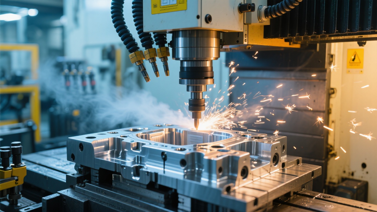
In mold manufacturing, “surface finish” is not a cosmetic metric—it is a functional requirement tied to release performance, polishing time, part appearance, and downstream cycle stability. For high-end tooling, a common target after finishing is Ra 0.2–0.4 μm on visible surfaces, with even tighter expectations on optical or glossy parts. Yet many shops still struggle with micro-chatter, thermal drift, inconsistent tool marks, and time-consuming handwork.
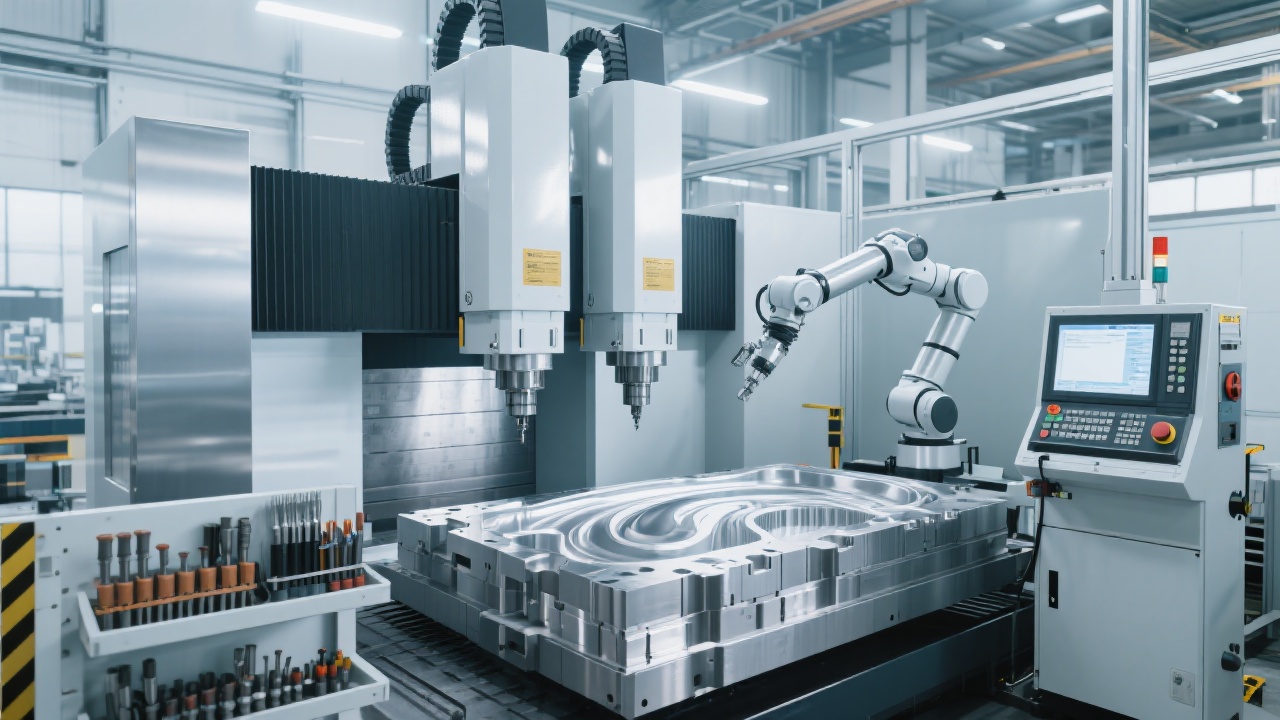
This tutorial breaks down the core technologies behind achieving repeatable, high-gloss mold surfaces using the Kaibo CNC high-precision high-speed milling machine GJ8070—with emphasis on Fanuc CNC control, a HSK high-speed spindle, and a double-column vertical structure. It also includes practical parameter guidance and verification methods engineers can apply immediately on the shop floor.
Mold surfaces reveal every weakness in the machining system. When finishing hardened steel (often HRC 48–56) or pre-hardened grades like P20, the gap between “acceptable” and “production-grade” finish is usually decided by stability at the micron level. Typical challenges include:
Often triggered by low dynamic stiffness, spindle/tool interface flex, or aggressive stepovers that excite resonance.
Small temperature changes shift spindle growth and geometry, causing ripple and “banding” on finishing passes.
Servo mismatch and corner behavior can leave facets, scallops, and inconsistent gloss on 3D freeform areas.
The practical goal for decision makers is not only a lower Ra number, but a predictable finishing window: stable heat behavior, repeatable gloss across cavities, and less manual polishing. That is where the GJ8070’s control, spindle, and structure must work as one system.
In high-speed finishing, the CNC controller is not a “command sender”—it is the real-time orchestrator of geometry, acceleration, and compensation. A modern Fanuc control system is widely used in mold shops because of its consistency in servo response and mature functions for high-accuracy contouring.
Freeform surfaces depend on continuous interpolation. When acceleration limits, corner handling, or feed fluctuation occur, the tool leaves a visible “texture” even if the CAM looks perfect. Fanuc high-precision contour control and feed management help maintain a more constant tool engagement, which typically reduces visible faceting—especially on shallow 3D slopes.
Mold finishing exposes geometric errors quickly: pitch error, backlash behavior, and axis squareness issues show up as waviness or uneven reflectivity. With controller-side compensation strategies (combined with proper calibration), shops commonly report measurable improvements in cavity consistency—often reflected as reduced rework time and fewer “polish-to-hide” corrections.
Even the best hardware cannot compensate for unstable toolpath intent. For finishing programs on hardened steel, engineers typically benefit from these practical moves:
If a finishing surface looks “almost right” but not mirror-consistent, the spindle-tool interface is often the hidden cause. The HSK high-speed spindle is engineered for high rigidity and repeatable clamping at high RPM, which helps reduce runout-related marks and micro-vibration.
| Spindle/Interface Factor | What It Changes in Cutting | Typical Effect on Surface Finish |
|---|---|---|
| Higher interface stiffness (HSK taper + face contact) | Less micro-deflection under load, more stable tool tip | Fewer chatter traces; more uniform gloss on slopes |
| Better high-RPM balance potential | Reduced vibration at 12,000–24,000 rpm finishing ranges | Lower “orange peel” texture; cleaner tool marks |
| Thermal stability design focus | More predictable spindle growth over long cycles | Less banding; improved cavity-to-cavity consistency |
A stable spindle gives engineers room to optimize cutting parameters for finish without flirting with resonance. For hardened mold steel finishing with small ball-nose tools (Ø6–Ø10 mm), many shops use a conservative baseline and then tune:
If you see ripple: reduce step-over first. If you see burnishing/darkness: avoid ultra-low feed in corners—improve smoothing and keep chip formation consistent. If you hear tonal vibration: adjust RPM by ±10–15% to move off resonance.
The most overlooked improvement is not “higher RPM,” but controlled engagement—the HSK spindle helps because it stays rigid when tool load changes across curvature transitions.
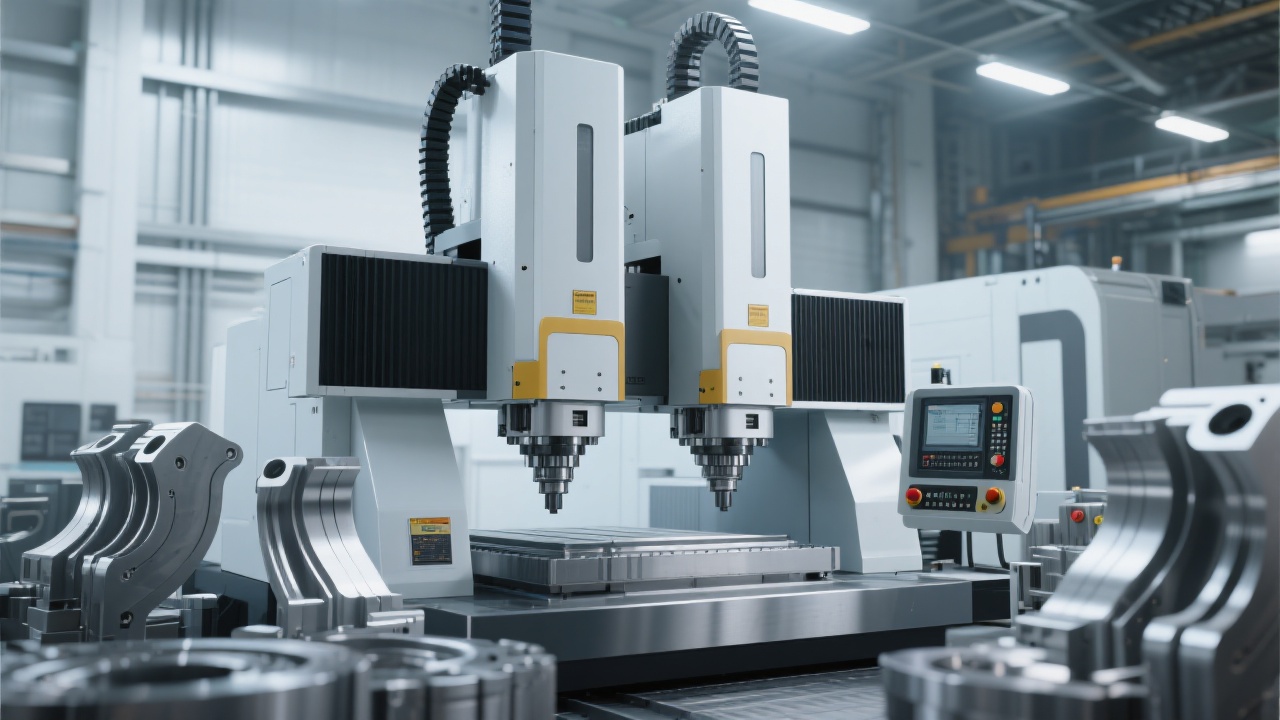
Mold finishing is a stability test. The double-column high-speed vertical structure (as used in the GJ8070 design approach) is valued because it improves rigidity and reduces torsional deformation under dynamic loads. In practical terms, it supports more consistent axis behavior when the cutter moves quickly along complex 3D paths.
Single-column machines can be excellent, but they are more sensitive to asymmetric cutting forces and long-reach finishing conditions (common in deep cavities). A double-column design generally distributes load more evenly, helping keep tool tip position stable during direction changes.
| Aspect | Double-Column Vertical | Single-Column (Conventional) |
|---|---|---|
| Directional consistency | More uniform finish when reversing or contouring | May show direction-dependent gloss |
| Long-reach stability | Better resistance to micro-chatter in deep cavities | More sensitive to tool overhang |
| Micron-level repeatability in finishing window | More stable across long cycles | Can be affected by localized flex/heat zones |
High-gloss finishing is usually won before the machine ever starts—by controlling stock, tool condition, and motion intent. Below is a workflow that aligns control behavior, HSK spindle strengths, and structural stability.
Many finishing defects come from uneven leftover material. A semi-finish pass that leaves a uniform allowance can significantly reduce tool load spikes. As a shop baseline, leaving 0.05–0.12 mm stock for finishing often produces more predictable results than trying to finish from inconsistent roughing remnants.
For 3D surfaces, strategies that reduce sudden engagement changes typically win:
Before running the finishing program, engineers can “pre-diagnose” finish risk with a short checklist:
A single Ra reading can hide problems. Many mold teams use a combination of: Ra measurement (e.g., target 0.2–0.4 μm for high-gloss areas), visual gloss consistency checks under consistent lighting, and process repeatability across cavities or inserts. When the machine-control-spindle-structure chain is stable, polishing time often drops noticeably—shops commonly aim for 20–40% reduction on demanding surfaces after parameter and path tuning.
A common scenario in precision mold shops is a cavity that machines quickly but demands excessive manual finishing due to inconsistent texture in shallow slopes and corner transitions. In production practice, the improvement path is usually not a single change, but a small set of coordinated adjustments:
In many real mold programs, once the finish becomes consistent, the shop gains a second benefit: cycle time becomes easier to predict, because operators stop “babysitting” the last 10% of the job.
If your team is evaluating high-precision equipment for mold finishing, the fastest way to reduce risk is to compare tooling strategy, control settings, and spindle/structure fit against your actual materials and surfaces. A detailed reference can shorten trials and help standardize parameters across projects.
Includes: recommended finishing parameter windows, stability checklist, and process notes for reducing polishing time—built for engineering review and decision-stage evaluation.


